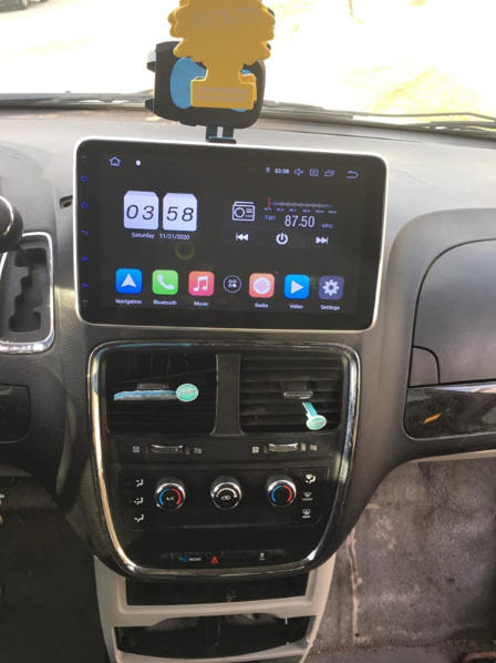
I installed this Pumpkin Android 10 single din car stereo on my 1999 Chevrolet Blazer and I’m surprised how easy it was. The touch screen is good, fairly responsive and stable mounted. Easy to set up and assemble.
It boots up super fast and I can rotate the screen and I can detach the screen so I don’t have to worry about theft to my 1999 blazer and I just put another one in my 2014 Caravan makes it look like a newer model.
The stereo is very sleek and stylish. We had no issues with installation and noticed a big difference in sound from the stock stereo. We’ve downloaded navigation apps, Spotify, and a few others to customize usage. We even played a video through Google Movies while using our cell phone as a Hotspot.
The customer service is #1! They are very responsive to all my questions.
If you’re looking to upgrade your factory radio, check this unit out. You’ll love it!
Video tutorial on how to install a double din android head unit in a first generation Toyota Tacoma. This head unit is made by Pumpkin, this tutorial will also cover how to install the back-up camera, navigation antenna, hands free microphone, and wifi antenna.
Supplies:
-ratchet with socket set
-screwdriver set
-wire cutters
-pliers
-wire strippers
-soldering iron
-heat gun
-shrink tube
-cable ties
-split loop casing
-file
-electrical tape
-butyl tape
-nylon trim tool
-hot knife or rotary tool with cutting disk
Step 1: The Head Unit
Here I have the Pumpkin’s head unit with an Android 9.0 interface, 8 core processor, 4gig of RAM and 32gig of storage. As you can see the comparison between the new head unit and the factory Toyota unit, it will fit in the dashboard with slight modifications. The factory mounting brackets also work with a mild modification as well. Included with the head unit is iso harness, I have already installed the Toyota specific harness which you’ll see in a bit, micro USB cable, extended USB cable, double USB cable, wifi antenna, hands-free microphone, back up camera, video cable for the backup camera, generic brackets with fasteners, and GPS antenna.
Step 2: Disassembly of the Interior
First is disconnecting the battery as we are working with the electrical system.
Remove the lower trim panel below the radio bezel. When I bought this truck, the interior was partially apart and some fasteners were missing so I’ll try to do my best to cover what’s missing. This trim piece should have two push-in clips, one on each side as shown by the exposed holes. Push in the center of the clip, then remove, and the panel can be lifted out. Next is disconnecting the electrical components on the rear, for this, I have two 12v power ports and the factory security led.
Remove the ashtray, depress the top metal portion and pull straight out. There will be a Phillips screw on the bottom which needs to be removed. For the HVAC panel, pull off the rotational knobs. They simply slide out of their location, they have an alignment groove so their position can’t be mixed up. If your fingers are too large, use a nylon trim tool to unclip the HVAC panel. Start from the outer hole and move your way across the panel. Remove the two Phillips screws hidden behind the HVAC panel holding on the bezel.
Using a nylon trim tool, you can start at the top or bottom, it doesn’t really matter, carefully remove the radio bezel. There will be various clips around the trim, take your time, especially in the cold as you can crack the plastic. Disconnect the plug on the rear for the passenger airbag switch. The yellow connector has a spring-loaded locking latch that needs to be pushed back when disconnecting.
Disconnect the cigarette lighter at the bottom. Then remove the light in the ashtray which pulls out, I used pliers for added grip.
Make sure you remove the cd if it’s in the radio as you won’t be able to retrieve it after. I had to hook up the battery to get this. Then remove the four 8mm bolts, two on each side of the radio.
Pull the radio straight out. Pull out the antenna wire, it just slides into place. The plug electrical connector on the rear comes out in two pieces, there will be tabs which are depressed to unclip it, then remove.
The wifi antenna will be installed behind the pillar trim, just like I did for the Ranger installation. To remove the pillar trim on the Tacoma, pop out the two fastener covers using a small standard screwdriver.
Then remove the two 10mm bolts holding on the pull handle and remove the handle. Pull off the door gasket which snaps into place, watch out for any butyl tape as it can be messy to clean up. Start at the top, pull off the trim, there will be two clips in behind. Then lift up as there is a tab on the bottom portion. If a clip stays in place, use pliers to compress, remove, and reinstall onto the plastic pillar trim.
Step 3: Installing the WiFi Antenna
The wiring needs to be running behind the dashboard, therefore the glove box needs to be dropped down. Compress in the sides of the glove box to disconnect the clips and pull down.
Next is removing the upper panel above the glove box. There will be three 10mm bolts holding in this piece. Two at the top corners and one behind the latch. Using a nylon trim tool, unclip the panel by the dashboard side, unclip it from the sides, and pull down. No need to disconnect the wires in behind.
Ensure the area is clean where you’re gluing on the antenna, I used isopropyl alcohol to wipe the surface. Remove the paper off the adhesive, then firmly press the antenna into place. The higher the antenna, the better the reception. Feed the wire between the dashboard and the pillar. You’ll need a light to view where the wire is inside the dashboard, I have feed the cable behind the metal reinforcement tubing closer to the firewall. The airbag is here, make sure the cable doesn’t interfere with it. There is also an HVAC duct actuator, so keep the wire away from that as well.
In order to keep the wire into place, I used butyl tape. Rip off a short portion, double it up if need be so it’s thicker and the wire can be pressed into it easer, then stick the wire into place. This will prevent the wire from rattling or having it pinched between the trim and clips.
The wire gets feed through the dashboard and over to the radio opening. Here’s a quick view of how I ran the wire. Use cable ties as needed to keep the installation clean and so the wire is kept safe, away from any moving components.
When done here, reinstall the panel above the glove box. Snap it back into place first. Then reinstall the three 10mm bolts. Don’t clip in the glove box just yet.
Snap the pillar trim back into place. Reinstall the pull handle, tighten the two 10mm bolts. Then install the two fastener caps. Push the door gasket back into place.
Step 4: Installing the Handsfree Microphone
Moving onto the driver’s side, this is where the handsfree microphone will be ran. First is removing the door gasket. Grab onto the top portion of the trim, pull out the unclip it and pull it up slightly to disconnect the alignment tab at the bottom.
Remove the knee panel on the driver’s side. This is the easiest way I’ve found the run the wires instead of reaching up in behind. There will be four 10mm bolts and I believe one Phillips screw under the dimmer switch, however mine is missing.
There will also be two more screws holding on the hood latch release. Pull off the panel, there will be various clips which will need to be disconnected. To run the back-up camera wire, I also need access under the carpet. Remove the four Phillips screws, then pull up the panel. Next is removing the kick panel, grab at the bottom and pull back. On the backside, you can see the alignment tabs.
Removing the map light, using a small standard screwdriver to pop off the center trim cap. Then using a nylon trim tool, unclip the cover prying from the base. Remove the four Phillips screws holding on the map light base. Don’t mix up the screws, there are two types here. Disconnect the wire plug on the rear, depress the tab and pull out.
I’m dropping the headliner down slightly so I can run the microphone wire. Remove the sun visor, there are two Phillips screws holding it onto place on the fixed pivot side. Unclip it from the lock and remove it. To remove the latch, there is another Phillips screw and finally, remove
If you have a sunroof, remove the rubber molding around the opening. I used the nylon trim tool to pop it out as it sits firmly in place. Pull the door gasket out at the top.
There will be bracing inside the roof where you can feed the wire, you may need the assistance of something stiffer to pull the wire through which I ended up using. There will be an opening just past the sun visor mounting point and this is where the wire exits before it going down the pillar. Considering there’s already a harness running down the pillar, I’m using cable ties to attach the microphone wire in place. Use as many as you need to keep the wire-free of getting pinched between the trim or clips. Trim the cable ties using side or bullnose cutters.
Feed the wire between the dashboard and pillar to the underside. Again it’s feed behind that metal tube brace on the firewall side. The wire is routed around the HVAC duct and follows the factory wiring to keep it safe away from any components where it can get damaged. The factor cable ties were opened up just enough to feed the wire through so there wasn’t any need for addiction cable ties. And finally, it’s over to the radio opening.
Now is reinstalling the pillar trim. Align the lower tab, then snap it back into place. Reinstall the sun visor clip, along with the sun visor. I left longer wiring exposed for the microphone, it can be tucked up inside the roof when the light gets installed. The tab left of the clip was removed using bullnose cutters. Then I touched it up with a file.
I have already predrilled a hole for the microphone to fit through. I used step drilled which does a clean up on the aluminum base. The size of the hole should match the microphone’s diameter.
Next is drilling the cover, again using the same process. I used the closest sized step drill I had and roughly aligned the hole so it doesn’t interfere with any components. The step drill does a very clean hole in the plastic too.
Once done, here you can see the finalized hole. This will allow for a clean factory looking install of the microphone in a generalized location for all the occupants. Feed the microphone through the base hole and screw it back in place. Make sure you don’t mix up the screws.
Then attach the microphone to the cover. If someone has an alternative way of mounting the microphone please share your ideas. I used some hot glue to hold it in place. If it does need to be removed, it can be, the glue should cleanly breakaway with a little force and it can be reapplied again easily.
Then feed the wire up into the roof and snap the cover back into place. Make sure that wire isn’t pinched anywhere. And snap in the cap around the mirror base. Once that little foam cover is in place, it’s in a safe place where it doesn’t interfere with any other components.
Step 5: Installing the Backup Camera
Moving onto the back-up camera now. The factory wiring is feed through the floor under the driver’s seat. Pull back the tape on the factory wiring, then insert the camera wire through here. Once you have the wiring finalized, the tape will need to be replaced so the grommet is sealed up again. The wiring is ran along the same route, so you’ll need to go under the truck. Considering it’s exposed to the elements, slip loop casing is highly recommended to protect the wire and you’ll see this casing in a moment.
Remove the tail light, there will be four Phillips screws holding it in place. There are two different sized screws here, so don’t mix them up. Pull out the tail light. The reverse camera requires a switched power source for the reverse lights and a ground. I will be cutting into both wires for the bulb. Using a razor knife, cut off about 3/4” of the casing to expose the conductor inside. Here I will be doing a lineman’s splice.
Strip the wires on the supplied power plug for the camera, red goes to the positive wire and black to the negative wire. This can be checked with a multimeter. Verify with your truck to be safe, for this truck I found green to be positive and white to be negative.
There also needs to be an additional power switching wire for the camera cable to the head unit. I did cut a length of 18 gauge red wire, again using a linesman splice to the green power wire, this is the same length as the camera power cable.
When the soldering is done, I used liquid tape to seal up the connection from any moisture or water. Due to the cold weather, I had to apply three coats. It’s best to warm up the liquid tape just by taking it indoors for the night as the cold can make it quite thick. Allow it to dry in between coats.
Those wires were ran through the tail light area and over behind the bumper. The video cable wire from the cab was routed behind the bumper and not inside the tail light area. The red wire was soldered to the video cable wire, then I used adhesive filled heat shrink for a waterproof connection.
Next, the wires were cable ties together to hold everything in place. Install the remaining section of split loop casing. This is available in a variety of sized, pick the sized which will fit around the connections. The split loop casing will protect these wires from the elements, such as road debris, water, snow, or whatever else that can jeopardize their condition.
Install the backup camera into place. Unlike the other version I installed which was fastened to the license place cover, this one just bolts up in place using the license place mounting holes. Just make sure the fasteners are long enough. Plugin the power and video wires.
Install the split loop casing, mine is a smaller diameter so one connection was installed in one section, then I just used an additional section for the other connector. Everything was closed up using electrical tape. The wires were pushed back behind the bumper and I used cable ties to hold it in place, keeping the wiring safe and clean.
Step 6: Installing the USB Ports
For the external dual USB hook up, this was ran in the glove box. You can mount this where ever you’d like, the center console would be another option. Using a step drill again, I picked the appropriate size for the wires and drilled a hole in the back of the glove box. On the Ranger, I left the wires handing down and cable tied inside the dashboard, however, the Tacoma doesn’t allow for this and the wires may fall in behind. The wires were then cable ties together and feed through the hole, over to the radio opening.
Step 7: Connecting the Main Harness
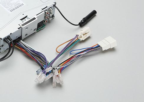
For the head unit’s wiring, I did cut the iso plug off the harness as it’s not compatible with this truck. The Tacoma does have quite a bit of room inside the dash, especially since the new head unit is shallower there shouldn’t be any issues with the pushing back all the wiring. All the wires which will be used were stripped. As a test run, I matched up all the wires which will be used, twisted them together, and then wrapped the conductor in electrical tape. This is a great way to ensure it’s working correctly in your vehicle. If you make a mistake after soldering than it’s harder to fix. I purchased a vehicle specific plug and play connector for the Tacoma. This method is highly recommended as you don’t have to cut up the factory wiring, the installation is much cleaner, and if you ever part ways with your vehicle, you can keep the head unit and reinstall the factory one. These plug and play harnesses can be purchased at your local auto parts store, some big box stores carry these, electronics store, or online.
The plug and play harness does come with a wiring diagram and pumpkin supplies a wiring diagram as well. Typically the colors are generic, but just verify everything to be safe. Pumpkin also has labels on their wiring making the process easier.
Next is removing the electrical tape. Unfortunately, with this plug and play harness, I couldn’t remove the extra plugs as it still leaves exposed wires and won’t allow for a cleaner install. Straighten out the wire strands. Crimped connected can be used, however, they do pose problems when not done correctly and they don’t always look as nice. I am using a color-coded shrink tube which is sized according to the wire gauge. Make sure the shrink tube is installed before the joint is soldered.
Work in a well-ventilated area, this is a flux core solder and the type of connections I’m using are known as a western splice. If you are seeking more information on soldering, I do have a video for that so be sure to check it out. Try to untangle the wires so everything lays fairly smooth before making the connections.
I soldered a few wires at a time, then heat the shrink tube. This is just a regular form of shrink tube, the connections are inside of the truck and it’s not exposed to an excessive amount of moisture so there’s no need for an adhesive filled shrink tube.
Once done, here you can see the finalized harness. Another couple of connections will be made in the truck and just before the finalized installation, the wiring will then be held together using cable ties. Any wires which won’t be used can have an adhesive filled shrink tube installed to close off the ends, however, this has already been done.
Step 8: Head Unit Fitment in the Bezel
The radio bezel did require some mild modifications to make it fit. The opening did require some filing, you need to remove about 1/16” or 2mm of plastic all the way around. Take your time, the outer plastic can be taped off if you wish to protect the outer finish. The corners are finished up with a rat-tail file to make a clean radius. When done, the opening can also be finished up with 800 grit sandpaper so there are no rough edges left from the file.
On the rear, I also used a rotary tool to cut away the away plastic brace on the top and bottom as it was interfering with the head unit’s frame. When done, you should be left with a light and smooth fitment, no need for any radio installation kits.
Remove the brackets from the factory Toyota radio. There will be alignment tabs one these brackets, one tab on each bracket did cause interference. I used pliers to break it off, then cleaned up the remainder of the tab using a file. These brackets are soft so it’s easy to file the break clean.
Using the supplied screws from Pumpkin, these are the correct length so they won’t push against any components inside, install the brackets. While there are four mounting holes, three can only be used for each bracket.
Step 9: Finalized Wiring and Installation
Back in the truck, for the reverse camera. For the head unit to turn on for video mode for the back up camera, the labelled camera wire gets connected to the red wire from the video cable. This connection was solder and had heat shrink applied. Those extra connectors on the harness, while they do have caps, they can still fall out so I wrapped then up in electrical tape to be safe. They are y’d off the harness so they still have power.
Next is organizing all the wiring using cable ties. This will keep everything clean, reduce the chance of the wiring becoming damaged, and it’s easier to push everything back into the dashboard. I have left the gps and wifi wires on their own just to reduce the chance of any interference.
The gps antenna has a magnetic base, it should be attached to a metal base to amplify the signal. I stuck it on the metal tube brace inside the dashboard, then as a little extra security, I used a cable tie to hold it into place. The antenna should have a direct line of view through the windshield. You may need to remove the hvac panel, it’s only held into place with three phillips screws.
For installing the head unit, typically I start with the longest wires first as they’ll be the easiest to install. Connect the gps and wifi antennas. These are a threaded connected and get snugged up with an 8mm wrench.
Connect the main plug for the head unit. Plug in the connection for the dual usb ports coming from the glove box. Connect the handsfree microphone jack.
For the back up camera, if you wish, you can double check to make sure everything works by hooking up the battery temporally and then turning on the head unit. The only function I didn’t hook up was the safety video wire to the parking brake switch. The reason for this is that the wires were quite hard to access underneath the dashboard. Leaving this disconnected may go against laws depending where you’re locked. An alternative is simply running a separate switch instead.
Push all the wiring into the dashboard, make sure nothing is getting pinched. You can reach up underneath the center area to direct any wires if needed. Then install the four fasteners and tighten.
Step 10: Putting Everything Back Together
Finally is reinstallation all the other components that were removed in reverse of removal. First is starting with the driver’s side knee panel, then moving onto the radio bezel trim, HVAC panel with knobs, and lower trim portion.
Make sure no wires are pinched while pushing the trim back into place. The clips may not align with the holes and that can prevent the trim from seating correctly so be mindful of that.
If you haven’t already, reconnect the battery.
Once done, here you can see how the head unit sits in the dashboard. There’s a tight fit around the perimeter of the unit, no need for bracket adjustments, it’s easily reachable and viewable for the driver, and the truck now has new tech features.
This installation guide walks you through the process of installing a new Android car stereo. Please read over these guidelines before beginning the installation in order to give yourself an idea of what to expect.
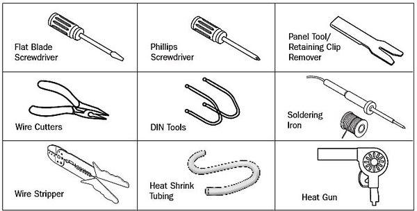
Tools Needed (depending upon vehicle)
Remove the factory stereo
When installing a new stereo in your car, your first step will be to remove the old stereo. Pay close attention to the steps involved, for the process for installing your new stereo will be the same, but in reverse.
For detailed information on how to remove the factory stereo in a specific vehicle, refer to your Crutchfield MasterSheet™ instructions, if available. They will walk you through the process step-by-step. Otherwise, you may use the general guidelines below.
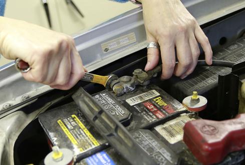
Before you begin, start by setting the parking brake and removing the negative cable from the car battery to prevent accidentally short circuiting something.
Disconnect your battery’s negative terminal before any installation job to protect your electrical system..
Your factory stereo will be mounted in one of two ways:
secured in a metal mounting sleeve by spring clips
bolted to the dash with brackets
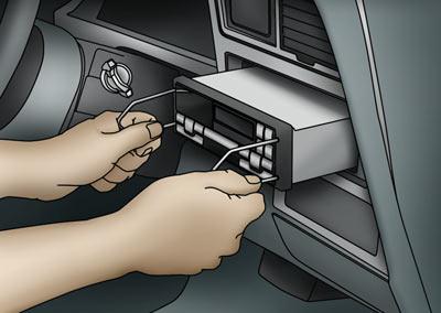
Spring clip mounting
If the stereo is held in by spring clips, you’ll need a pair of DIN tools. Insert the DIN tools into the holes on eitter side of the unit until a click is heard. The tools serve to release the spring clips and also hook onto the sides of the stereo so that you can pull it out easily. Spread the tools apart slightly then pull the stereo out of the dash.
These DIN tools are used to remove the factory stereo from a 2000 Ford Expedition.
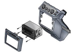
Bolted in place
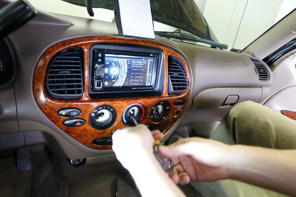
Sometimes, accessing the stereo requires the removal of one or more trimpanels from the dash. You may have to (carefully) pry the plastic trim away from the dash (which is often secured by hidden pressure clips), or locate and remove bolts to disassemble other pieces of panel. Once you have gained access to the factory stereo, removal should be obvious. The audio player will almost always be secured by four screws, sometimes bolted directly to the front of the dash, other times secured to side brackets. Remove the screws and pull the stereo from the dash.
Four bolts and a pair of side brackets attach the stereo to the dasgh in a 1998 Toyota Sienna.
American cars built before the early 1980s often came with a “shaft-style” stereo, which secured to the dash via nuts and washers to the right and left knobs. A shaft-style stereo must be installed from behind the dash. Getting it into position is the tricky part, since your vehicle’s wiring,heater controls, and ductwork may be in the way.
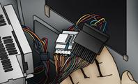
Unplugging the factory stereo
If your vehicle has (or once had) a factory stereo, or if it was pre-wired with a “stereo prep” package, there should be at least one plastic wiring harness behind the stereo opening. This plug(s) connects the stereo to your vehicle’s electrical system, and also makes the speaker connections. You will need to unplug the factory stereo from the wiring harnesses, and unplug the antenna to complete the removal process.
Connect the wiring
If Crutchfield carries a custom wiring harness for your vehicle, you can use it to connect your new stereo to your vehicle’s factory wiring harnesses. This will ensure that everything works seamlessly, just like the factory stereo did.
A custom wiring harness makes installing a new stereo much easier.
If a harness is not available for your vehicle or if the factory stereo plug was cut off, you’ll need to identify each of the stereo wires and connect them to the corresponding wires of your new stereo.
Crimping, Posi-Product™ connectors, and soldering
Decide how you want to connect the wires together. Crimping is fast and fairly simple. If you crimp the wires together, be sure to use the correct size crimp connector — typical in-dash stereo wires are 18-gauge, but a few use heavier gauge power and ground wires. There are several types of crimp connectors, including bullet connectors, butt connectors, or crimp caps.
Posi connectors offer a quick and secure twist-on connection for wires, and they can be re-used. Like crimping, you’ll want to make sure you have the right wire gauges for the job.
Posi-Product connectors provide secure connections for your wiring.
Soldering creates a permanent, professional connection that ensures maximum current transfer. We strongly recommend that you use heat-shrink tubing and a heat gun to insulate the soldered connection. Avoid taping the wires together — the tape will dry out and fall off, exposing the wires and making it only a matter of time before something shorts out.
Power
Usually, it is best to make all of the new stereo‘s wiring connections via the wiring harness, but if you have to make a direct power connection, you’ll need to know the difference between “switched” and “constant” power.
A switched power source is only on when the ignition is keyed — connect your new stereo’s main (switched) power lead to a switched power source, so that the stereo will turn off when you turn off the car, and not drain your vehicle’s battery.
A constant power source is always on — connect your new stereo’s memory lead to a constant power source, so that you don’t lose your stereo preset, sound shaping, and clock settings every time you turn off the vehicle.
A rare few high-powered stereos require you to make a direct constant power connection at the positive terminal of your vehicle’s battery. This requires a heavier gauge power wire, an in-line fuse (usually included), and a ring terminal to connect the power wire to the battery clamp. You will have to route the power wire through the vehicle firewall and into the engine compartment in order to make the connection at the battery.
Ground
A good ground connection is vital for proper stereo performance. If you are not using a custom wiring harness, look for a bolt, screw, or wire that contacts the bare metal of your vehicle’s chassis. Loosen the bolt, slip the ground wire underneath (this is almost always a black wire), then tighten the bolt. If your ground wire doesn’t contact bare metal, your stereo won’t operate. A loose or weak ground connection can result in signal noise interfering with your music.
In-dash video wiring
If your new Android car DVD player has a video monitor built in, you will also need to connect a wire to your emergency brake wire. This wire acts as a switch to turn on the video monitor when the parking brake is engaged. Follow the instructions included with your in-dash monitor to locate the emergency brake ground wire.
Install the new stereo
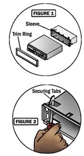
If the original stereo was bolted into the dash, you might need to remove the mounting brackets from the sides of it and attach them to the sides of your new stereo. More likely, you will need a mounting kit (which may include a trim ring, a dash insert, brackets, a faceplate, and/or a metal mounting sleeve) to install the stereo (Figure 1).
If a mounting kit is required, install it first. Then slide the new stereo’s metal mounting sleeve (if included) into the kit. Secure the metal sleeve by using a screwdriver to bend the sleeve’s metal tabs into place (Figure 2).
Once the dash opening is ready for the new stereo, hold the stereo near the opening. Connect the stereo wiring adapter to the vehicle’s wiring harness and plug in the antenna cable.
Slide the car stereo Bluetooth into the dash opening, but don’t fasten it down just yet. First, test the stereo to make sure everything is working properly. It’s easier to fix a problem while everything is still exposed. Turn on the power and try each source (AM, FM, CD, USB, etc.). Then adjust the balance and fader settings to check that each speaker is working. Once you’re sure the stereo is wired and working properly, finish securing it in the dash and reinstall any pieces of dash trimpanel that you removed.
Installing a backstrap
A mounting bracket — or backstrap — is often included with new stereos. For most installations, a backstrap usually is not a necessary part of the installation process. However, it can be useful to help support the stereo in your dash; it also helps reduce vibration. One end of the backtrap attaches (with a screw) to the rear of the stereo. The other end attaches to an existing bolt or screw behind the dash. Just bend and shape the backstrap as necessary to enable mounting.
You might need to use a backstrap to support the rear of your new stereo.
Can you do it?
If your vehicle has an upgraded version of the factory sound system or an integrated stereo/climate control panel, you will probably need a special “OEM integration” adapter in order to install a new stereo. An adapter allows you to use a new stereo with your existing speaker system.
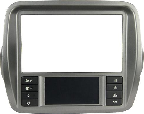
This adapter allows you to install an aftermarket stereo in a 2010-up Chevy Camaro’s dash panel, while maintaining all heating, ventilation, and air conditioning controls.
Evaluation
By now you should have some idea of what is involved in replacing your factory stereo with a new, better, aftermarket stereo. The next step is to see if Crutchfield has a MasterSheet™ for your vehicle. That’s a set of installation instructions custom designed for your specific vehicle. It will describe every step of the process and tell you where to find every screw you need to remove for the installation. A MasterSheet™ takes all the guesswork out of the installation.
Even without a Crutchfield MasterSheet™, most people can install an in-dash stereo without much trouble, using just the tips in this article. This in turn leads to a savings in installation fees ($50 is common, and often it’s more). But if you would rather not tackle the task, there are competent and highly trained professional stereo installers in every town where you’d find teenagers and cars.