Let’s face it, most vehicles in the 2000s era have head units, or just car stereo technology in general, that’s outdated. Bluetooth was just catching on (although aux inputs were the thing), GPS navigation was a luxury and touchscreen head units were few and far in between from the factory. At the time, the 05 CLK 320 was a great, stylish and luxurious car but to bring it into the modern age it needs an upgrade.
We sought a price-friendly but powerful head unit to upgrade our 2005 CLK 320’s stereo and bring it up to speed with some of the latest technology to make it a decent commuter. We were thrilled when PUMPKIN reached out to us with a unit that we could test for them.
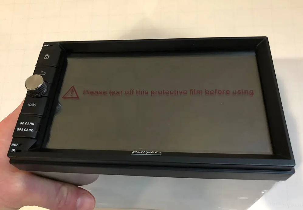
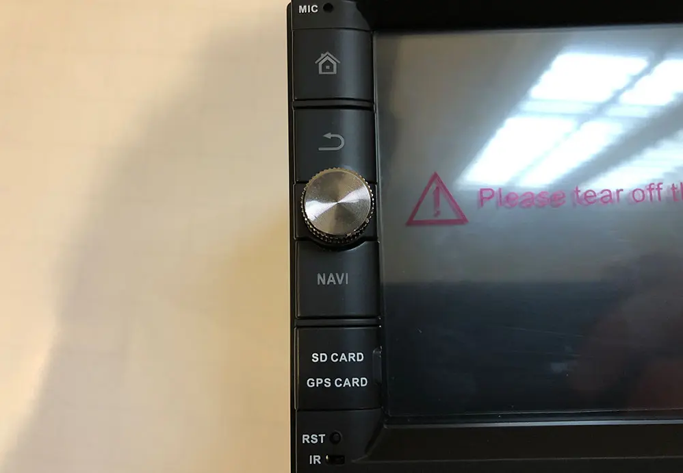
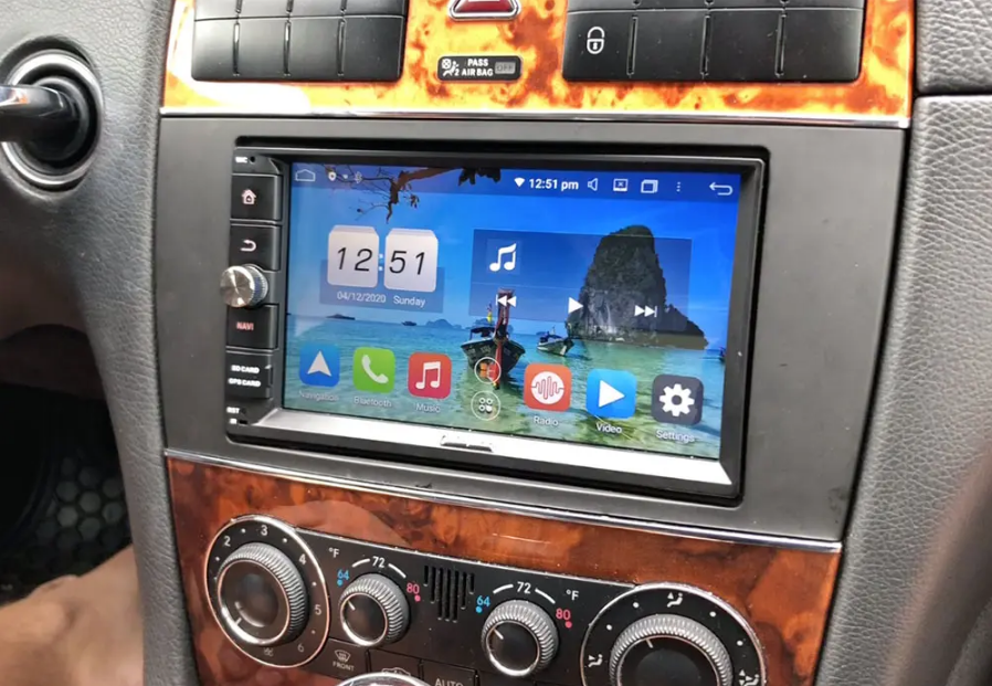
The Head Unit – PUMPKIN A ndroid 9.0 Double Din
This installation will apply to nearly all double din touch screen head units, Apple CarPlay and Android Auto, or double din multimedia head units regardless of the unit we chose to install. If you’re looking to match the product we used in this installation, the head unit that we chose was PUMPKIN’s Android 9.0 Double Din, model AA0495B. You can find it directly on Pumpkin’s website here.
About PUMPKIN
PUMPKIN is a China-based manufacturer that was founded in 2014. They’re primarily focused in the European market, but also have a presence in the U.S. Their staple products include OEM replacement head units, double and single din head units, portable and dual screen DVD players along with headrest monitors. Most of their products are Android systems, including the one that we installed in our CLK 320.
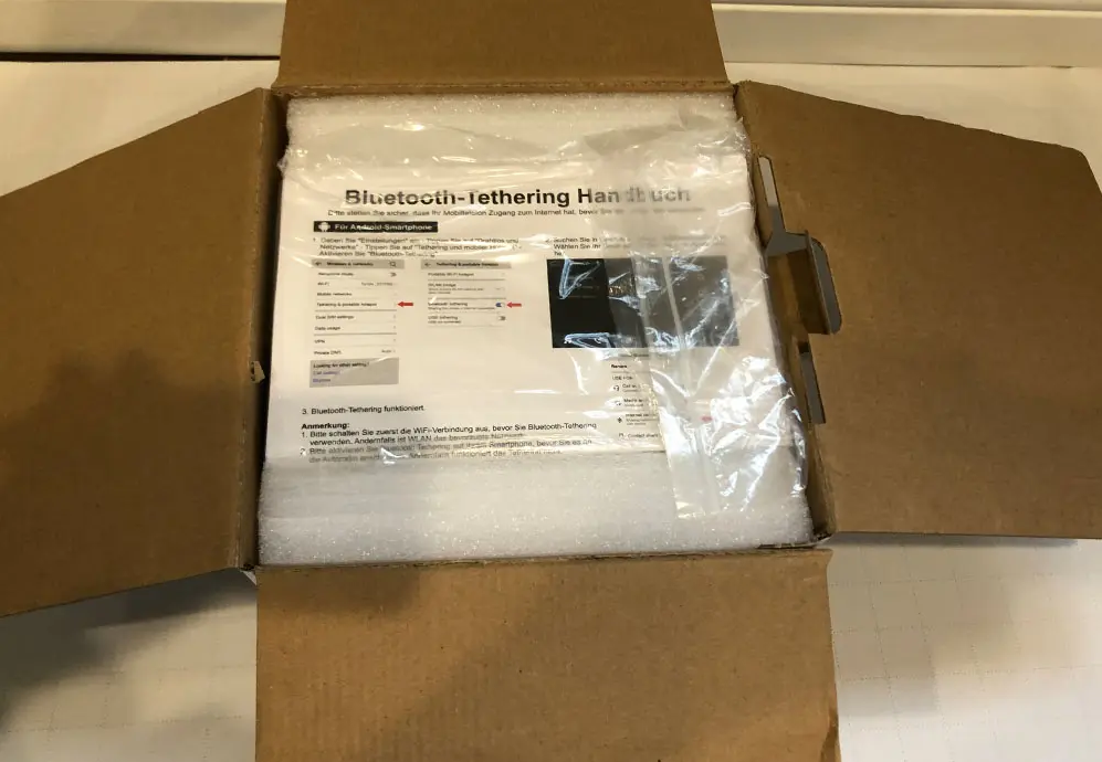
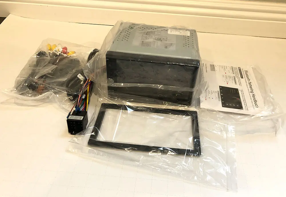
Out of the Box
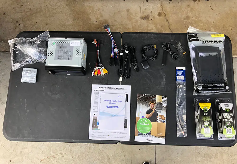
In the box, the PUMPKIN head unit comes with:
1x Android Head Unit
1x ISO cable
1x external microphone
1x USB+ Mic cable
1x Audio Output cable
1x wifi antenna (4.9ft)
1x GPS antenna
1x AUX Input cable
1x Cam-in cable
1x Installation Accessories (wire harnesses)
1x User manual
Installation In 2002 – 2005 Mercedes CLK320
Note that the instructions and parts below are for a CLK320 WITHOUT Harman Kardon. If you’re looking to install a head unit in a CLK320 with Harman Kardon/amplified stereo you’ll need a special harness. It’s all-in-one so the only thing you’ll need to do is substitute this harness for the Axxess harnesses that we show below.
Necessary Parts for the Installation:
Head unit (of course) – We used our PUMPKIN double din head unit
Axxess XSVI-9005-Nav harness – adapts the OEM Mercedes head unit wires to the aftermarket head unit. Also creates an accessory 12v power. Without this harness and adapter, you’ll have to find another source for wiring your accessory turn-on power. This harness also plugs right into the ASWC-1 below.
Axxess ASWC-1 – Steering wheel control interface. Optional if you want to retain steering wheel controls.
Metra 40-EU10 – Adapts the OEM radio antenna plug to an aftermarket plug.
Metra 99-874B – Dash kit that adapts the double-din to the factory dash cutout.
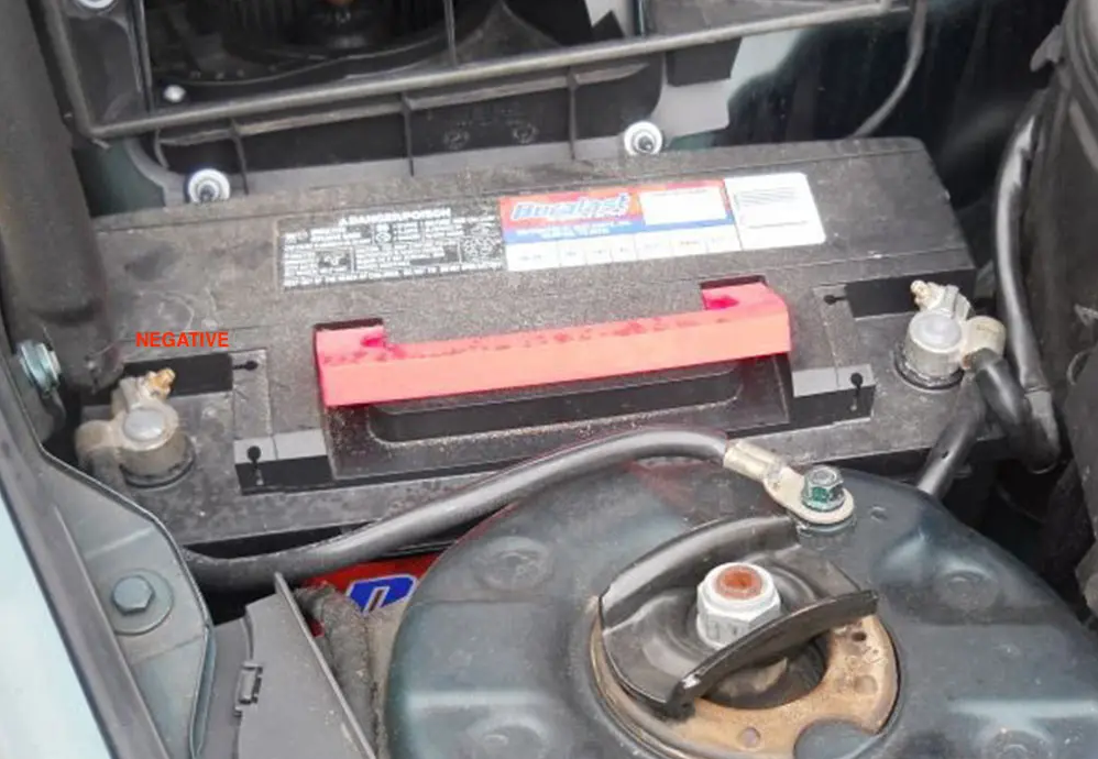
Step 1: Disconnect Your Battery
First things first – you’ll need to disconnect your battery so that you don’t blow any fuses during your install. The battery in the CLK 320 is located on the passenger side of the car under the hood, just in front of the firewall. Remove the negative terminal on the left hand side of the battery (when facing it).
Step 2: Remove Dash Trim
Start with the console trim piece that surrounds the shift boot. Open up the ash tray and pull upwards starting from the front, working your way backwards. Next, gently pry the back side of the shift boot trim upward and work your way to the front. Once the boot trim has been removed, you can then feed this trim piece through the hole in the console trim piece and fully remove the console trim piece.
Next, you’ll remove the ash tray by pulling the two pronged-like clips on the bottom towards you and lifting it out of the dash.
Now that the ash tray is out of the car, you’ll have access to two torx screws below the climate control unit. Remove these two screws and pull the climate control unit out. Note there are two clips at the top corners that are holding it in that’ll ‘pop’ out as you pull it. Once the unit is removed, you’ll pull the connected wires – there are two to remove. Remove these two wires and remove the unit from the dash.
With the climate control removed, you now will have access to the two bottom screws that hold in the head unit. However, there are two above the unit as well so before you remove them, you’ll need to pull the trim panel and buttons off that are above the head unit. To do this, press the cup holder to extend the cupholder out. Using your fingers, pull on the inner right hand corner of the panel to unclip the corner, then work your way to the left. With the trim piece removed, unclip the wire harness from the back of the unit in order to remove it entirely.
Once this panel is out you’ll be able to access the two top screws to the head unit.
Step 3: Unscrew and Remove OEM Head Unit
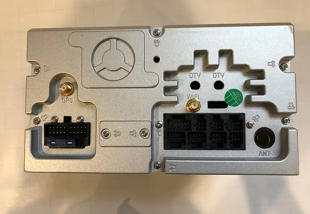
Now that all the trim pieces are removed, you’ll have access to the four torx screws to pull the head unit out. Remove these screws and pull the head unit straight out to get access to the harnesses on the rear side of the head unit. Remove the large harness on the left of the unit by pinching the clip and pulling the bar downwards. This harness is large, and includes multiple sub-harnesses. The whole thing should come out. Then, unclip the two wires on the right of the unit by pressing on the top of the clip. Once all of the wires from the back of the unit have been removed, pull the head unit from the dash and remove it from your car.
Step 4: Prepare Your Wiring Harness & Head Unit
With your OEM head unit out and your dash ready for your new head unit, the next step is to prepare your wire harness adapter and your head unit for installing in the car. In our case, the adapting Axxess XSVI-9005-Nav and ASWC-1 plugged together, but we needed to adapt the aftermarket head unit wire harness to the vehicle adapting Access harnesses. To do this, we soldered each of the wires from one harness to the corresponding wire on the other. Typically, all of the colors will match but just in case, we have a list of all of the aftermarket wire colors to help guide you.
Couple things to note:
Brake wire – we typically just combine this with the main ground wire so that any features that are restricted by movement will be unlocked. Note that some units are smarter and use GPS to sense motion but this will typically open up any video or other features that are locked when your vehicle isn’t in park.
Steering wheel control – the ASWC-1 comes with a 3.5mm plug that will adapt to most head units by plugging into the rear of the unit. However, in some cases it needs to be further adapted into two wires: Key 1 and Key 2. These two wires will need to be connected to the corresponding Key 1 and Key 2 wires from the aftermarket head unit harness.
You can either solder each of the wires like we did, or use crimps and a crimping tool. Here’s what the resulting wire harness looked like:
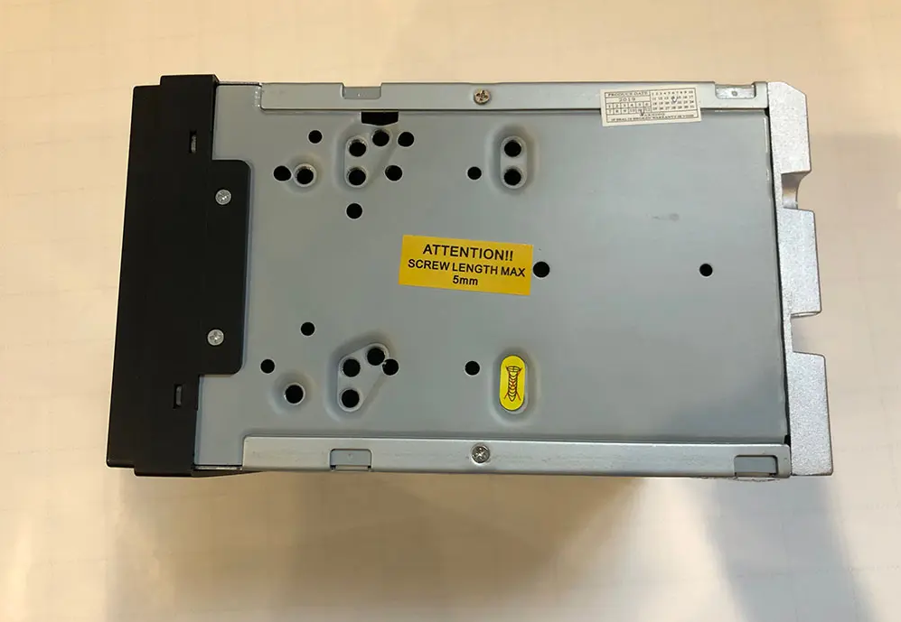
To prepare your head unit to be mounted into the dash, you’ll need to mount your new aftermarket head unit to the Metra 99-874B dash kit. Do this by mounting the two left and right mounting plates to the head unit losely. Once they’re mounted, place the adapting dash trim over the face of the head unit to check your mounting point and that the unit sticks out as far as you would like it. If your satisfied, tighten the side plates and mount the trim piece to the side plates.
Step 5: Wiring Accessories – Antennas, USB & Microphone
Before you mount your new head unit in the dash, you need to make sure that all the wiring that plugs into the back of the head unit are wired into the back of the dash. This includes things like:
USB chords
GPS and WiFi Antennas
Microphone
The PUMPKIN head unit that we chose had all of the above so we wired up all three to the back of the dash before we re-installed our new head unit.
USB Chords
Our head unit came with two usb inputs that are wired up to the back of the head unit, so we had to choose a spot for the new USB chords to go and then wire them. In our CLK 320, we decide to utilize the ash tray below the head unit. No need to cut holes, simply pull the removable ash tray component out of the ash tray cubby and feed the wires into the ash tray cubby.
GPS & WiFi Antennas, Microphone
For all three of these components, we fed the wire from the dash area, underneath the steering wheel and to the far left side of the dash. To do this, there’s a panel above your feet that has two torx screws. Remove the torx screws and pull the panel to gain access to behind the dash under your steering wheel. Then, remove the panel on the left hand side of the dash that faces the door (when closed). Feed the wires from the central dash area through to the left side of the dash. We used zip tie to fasten the wire under the dash.
Once your GPS, WiFi and microphone (or any combination of the three) are through the dash and out of the side panel of the dash, we mounted the WiFi antenna straight to the dash right next to the fuse box. Continue to feed your GPS and Microphone up through the pillar by placing the wire in between the pillar panel and the rubber seal. Tuck your wires behind the pillar panel.
At the top of the pillar, feed your wires across and to the window. We typically mount our microphones in the top left hand side of the windshield and clip it in between the head liner and the windshield. For the GPS, continue to tuck the wire behind the head liner through to the left hand side of the rear view mirror. This is where we mounted our GPS unit.
Step 6: Installing Your New Head Unit
Finally, you’re ready to re-install your head unit and connect all of the wires. One last step before you place start connecting your head unit and screwing it in – use the Metra 40-EU10 to connect to the black antenna wire that was connected to the back of your OEM head unit (there was a black and a yellow/tan one – use the black). Plug the antenna wire into the back of the unit.
Now, move on to the microphone, GPS and WiFi connections (if your head unit has them). Connect these to the back of the unit. Finally, connect your new adapting harness with the Axxess modules connected and tuck the modules behind where the climate control would go. You’ll need to make as much room behind the head unit so that it will have enough depth to mount. If you don’t tuck your wires and modules neatly out of the way of the back of the head unit it will not have enough room to mount flush.
At this point, you should have all of your wires connected and the head unit should not be fully mounted yet. Re-connect your vehicle’s battery and test out your unit. You’ll want to check:
Power – obviously this is the most important first-check
Radio – check sound and that the radio has reception
GPS – If your unit has GPS ensure that it has signal
Bluetooth call – make sure that your new microphone works
USB – check that your USB connection works
WiFi – in our case we had a WiFi antenna, check that you have signal and that you can connect to a WiFi network
Test general features – Roam around the features of your new head unit. Make sure that nothing is defective before you permanently re-install it!
Once you’ve checked your unit and everything is confirmed working, you can begin mounting it back. Mount the unit by screwing the four torx screws.*Note – the climate control has clips that you’ll need to remove from the old head unit. Take these clips and place them on the back side of the screw holes on your new unit BEFORE you screw it in.
Move on to the trim pieces, reversing the process that you took to remove them. And your finished product:
Video tutorial on how to install a double din android head unit in a first generation Toyota Tacoma. This head unit is made by Pumpkin, this tutorial will also cover how to install the back-up camera, navigation antenna, hands free microphone, and wifi antenna.
Supplies:
-ratchet with socket set
-screwdriver set
-wire cutters
-pliers
-wire strippers
-soldering iron
-heat gun
-shrink tube
-cable ties
-split loop casing
-file
-electrical tape
-butyl tape
-nylon trim tool
-hot knife or rotary tool with cutting disk
Step 1: The Head Unit
Here I have the Pumpkin’s head unit with an Android 9.0 interface, 8 core processor, 4gig of RAM and 32gig of storage. As you can see the comparison between the new head unit and the factory Toyota unit, it will fit in the dashboard with slight modifications. The factory mounting brackets also work with a mild modification as well. Included with the head unit is iso harness, I have already installed the Toyota specific harness which you’ll see in a bit, micro USB cable, extended USB cable, double USB cable, wifi antenna, hands-free microphone, back up camera, video cable for the backup camera, generic brackets with fasteners, and GPS antenna.
Step 2: Disassembly of the Interior
First is disconnecting the battery as we are working with the electrical system.
Remove the lower trim panel below the radio bezel. When I bought this truck, the interior was partially apart and some fasteners were missing so I’ll try to do my best to cover what’s missing. This trim piece should have two push-in clips, one on each side as shown by the exposed holes. Push in the center of the clip, then remove, and the panel can be lifted out. Next is disconnecting the electrical components on the rear, for this, I have two 12v power ports and the factory security led.
Remove the ashtray, depress the top metal portion and pull straight out. There will be a Phillips screw on the bottom which needs to be removed. For the HVAC panel, pull off the rotational knobs. They simply slide out of their location, they have an alignment groove so their position can’t be mixed up. If your fingers are too large, use a nylon trim tool to unclip the HVAC panel. Start from the outer hole and move your way across the panel. Remove the two Phillips screws hidden behind the HVAC panel holding on the bezel.
Using a nylon trim tool, you can start at the top or bottom, it doesn’t really matter, carefully remove the radio bezel. There will be various clips around the trim, take your time, especially in the cold as you can crack the plastic. Disconnect the plug on the rear for the passenger airbag switch. The yellow connector has a spring-loaded locking latch that needs to be pushed back when disconnecting.
Disconnect the cigarette lighter at the bottom. Then remove the light in the ashtray which pulls out, I used pliers for added grip.
Make sure you remove the cd if it’s in the radio as you won’t be able to retrieve it after. I had to hook up the battery to get this. Then remove the four 8mm bolts, two on each side of the radio.
Pull the radio straight out. Pull out the antenna wire, it just slides into place. The plug electrical connector on the rear comes out in two pieces, there will be tabs which are depressed to unclip it, then remove.
The wifi antenna will be installed behind the pillar trim, just like I did for the Ranger installation. To remove the pillar trim on the Tacoma, pop out the two fastener covers using a small standard screwdriver.
Then remove the two 10mm bolts holding on the pull handle and remove the handle. Pull off the door gasket which snaps into place, watch out for any butyl tape as it can be messy to clean up. Start at the top, pull off the trim, there will be two clips in behind. Then lift up as there is a tab on the bottom portion. If a clip stays in place, use pliers to compress, remove, and reinstall onto the plastic pillar trim.
Step 3: Installing the WiFi Antenna
The wiring needs to be running behind the dashboard, therefore the glove box needs to be dropped down. Compress in the sides of the glove box to disconnect the clips and pull down.
Next is removing the upper panel above the glove box. There will be three 10mm bolts holding in this piece. Two at the top corners and one behind the latch. Using a nylon trim tool, unclip the panel by the dashboard side, unclip it from the sides, and pull down. No need to disconnect the wires in behind.
Ensure the area is clean where you’re gluing on the antenna, I used isopropyl alcohol to wipe the surface. Remove the paper off the adhesive, then firmly press the antenna into place. The higher the antenna, the better the reception. Feed the wire between the dashboard and the pillar. You’ll need a light to view where the wire is inside the dashboard, I have feed the cable behind the metal reinforcement tubing closer to the firewall. The airbag is here, make sure the cable doesn’t interfere with it. There is also an HVAC duct actuator, so keep the wire away from that as well.
In order to keep the wire into place, I used butyl tape. Rip off a short portion, double it up if need be so it’s thicker and the wire can be pressed into it easer, then stick the wire into place. This will prevent the wire from rattling or having it pinched between the trim and clips.
The wire gets feed through the dashboard and over to the radio opening. Here’s a quick view of how I ran the wire. Use cable ties as needed to keep the installation clean and so the wire is kept safe, away from any moving components.
When done here, reinstall the panel above the glove box. Snap it back into place first. Then reinstall the three 10mm bolts. Don’t clip in the glove box just yet.
Snap the pillar trim back into place. Reinstall the pull handle, tighten the two 10mm bolts. Then install the two fastener caps. Push the door gasket back into place.
Step 4: Installing the Handsfree Microphone
Moving onto the driver’s side, this is where the handsfree microphone will be ran. First is removing the door gasket. Grab onto the top portion of the trim, pull out the unclip it and pull it up slightly to disconnect the alignment tab at the bottom.
Remove the knee panel on the driver’s side. This is the easiest way I’ve found the run the wires instead of reaching up in behind. There will be four 10mm bolts and I believe one Phillips screw under the dimmer switch, however mine is missing.
There will also be two more screws holding on the hood latch release. Pull off the panel, there will be various clips which will need to be disconnected. To run the back-up camera wire, I also need access under the carpet. Remove the four Phillips screws, then pull up the panel. Next is removing the kick panel, grab at the bottom and pull back. On the backside, you can see the alignment tabs.
Removing the map light, using a small standard screwdriver to pop off the center trim cap. Then using a nylon trim tool, unclip the cover prying from the base. Remove the four Phillips screws holding on the map light base. Don’t mix up the screws, there are two types here. Disconnect the wire plug on the rear, depress the tab and pull out.
I’m dropping the headliner down slightly so I can run the microphone wire. Remove the sun visor, there are two Phillips screws holding it onto place on the fixed pivot side. Unclip it from the lock and remove it. To remove the latch, there is another Phillips screw and finally, remove
If you have a sunroof, remove the rubber molding around the opening. I used the nylon trim tool to pop it out as it sits firmly in place. Pull the door gasket out at the top.
There will be bracing inside the roof where you can feed the wire, you may need the assistance of something stiffer to pull the wire through which I ended up using. There will be an opening just past the sun visor mounting point and this is where the wire exits before it going down the pillar. Considering there’s already a harness running down the pillar, I’m using cable ties to attach the microphone wire in place. Use as many as you need to keep the wire-free of getting pinched between the trim or clips. Trim the cable ties using side or bullnose cutters.
Feed the wire between the dashboard and pillar to the underside. Again it’s feed behind that metal tube brace on the firewall side. The wire is routed around the HVAC duct and follows the factory wiring to keep it safe away from any components where it can get damaged. The factor cable ties were opened up just enough to feed the wire through so there wasn’t any need for addiction cable ties. And finally, it’s over to the radio opening.
Now is reinstalling the pillar trim. Align the lower tab, then snap it back into place. Reinstall the sun visor clip, along with the sun visor. I left longer wiring exposed for the microphone, it can be tucked up inside the roof when the light gets installed. The tab left of the clip was removed using bullnose cutters. Then I touched it up with a file.
I have already predrilled a hole for the microphone to fit through. I used step drilled which does a clean up on the aluminum base. The size of the hole should match the microphone’s diameter.
Next is drilling the cover, again using the same process. I used the closest sized step drill I had and roughly aligned the hole so it doesn’t interfere with any components. The step drill does a very clean hole in the plastic too.
Once done, here you can see the finalized hole. This will allow for a clean factory looking install of the microphone in a generalized location for all the occupants. Feed the microphone through the base hole and screw it back in place. Make sure you don’t mix up the screws.
Then attach the microphone to the cover. If someone has an alternative way of mounting the microphone please share your ideas. I used some hot glue to hold it in place. If it does need to be removed, it can be, the glue should cleanly breakaway with a little force and it can be reapplied again easily.
Then feed the wire up into the roof and snap the cover back into place. Make sure that wire isn’t pinched anywhere. And snap in the cap around the mirror base. Once that little foam cover is in place, it’s in a safe place where it doesn’t interfere with any other components.
Step 5: Installing the Backup Camera
Moving onto the back-up camera now. The factory wiring is feed through the floor under the driver’s seat. Pull back the tape on the factory wiring, then insert the camera wire through here. Once you have the wiring finalized, the tape will need to be replaced so the grommet is sealed up again. The wiring is ran along the same route, so you’ll need to go under the truck. Considering it’s exposed to the elements, slip loop casing is highly recommended to protect the wire and you’ll see this casing in a moment.
Remove the tail light, there will be four Phillips screws holding it in place. There are two different sized screws here, so don’t mix them up. Pull out the tail light. The reverse camera requires a switched power source for the reverse lights and a ground. I will be cutting into both wires for the bulb. Using a razor knife, cut off about 3/4” of the casing to expose the conductor inside. Here I will be doing a lineman’s splice.
Strip the wires on the supplied power plug for the camera, red goes to the positive wire and black to the negative wire. This can be checked with a multimeter. Verify with your truck to be safe, for this truck I found green to be positive and white to be negative.
There also needs to be an additional power switching wire for the camera cable to the head unit. I did cut a length of 18 gauge red wire, again using a linesman splice to the green power wire, this is the same length as the camera power cable.
When the soldering is done, I used liquid tape to seal up the connection from any moisture or water. Due to the cold weather, I had to apply three coats. It’s best to warm up the liquid tape just by taking it indoors for the night as the cold can make it quite thick. Allow it to dry in between coats.
Those wires were ran through the tail light area and over behind the bumper. The video cable wire from the cab was routed behind the bumper and not inside the tail light area. The red wire was soldered to the video cable wire, then I used adhesive filled heat shrink for a waterproof connection.
Next, the wires were cable ties together to hold everything in place. Install the remaining section of split loop casing. This is available in a variety of sized, pick the sized which will fit around the connections. The split loop casing will protect these wires from the elements, such as road debris, water, snow, or whatever else that can jeopardize their condition.
Install the backup camera into place. Unlike the other version I installed which was fastened to the license place cover, this one just bolts up in place using the license place mounting holes. Just make sure the fasteners are long enough. Plugin the power and video wires.
Install the split loop casing, mine is a smaller diameter so one connection was installed in one section, then I just used an additional section for the other connector. Everything was closed up using electrical tape. The wires were pushed back behind the bumper and I used cable ties to hold it in place, keeping the wiring safe and clean.
Step 6: Installing the USB Ports
For the external dual USB hook up, this was ran in the glove box. You can mount this where ever you’d like, the center console would be another option. Using a step drill again, I picked the appropriate size for the wires and drilled a hole in the back of the glove box. On the Ranger, I left the wires handing down and cable tied inside the dashboard, however, the Tacoma doesn’t allow for this and the wires may fall in behind. The wires were then cable ties together and feed through the hole, over to the radio opening.
Step 7: Connecting the Main Harness
For the head unit’s wiring, I did cut the iso plug off the harness as it’s not compatible with this truck. The Tacoma does have quite a bit of room inside the dash, especially since the new head unit is shallower there shouldn’t be any issues with the pushing back all the wiring. All the wires which will be used were stripped. As a test run, I matched up all the wires which will be used, twisted them together, and then wrapped the conductor in electrical tape. This is a great way to ensure it’s working correctly in your vehicle. If you make a mistake after soldering than it’s harder to fix. I purchased a vehicle specific plug and play connector for the Tacoma. This method is highly recommended as you don’t have to cut up the factory wiring, the installation is much cleaner, and if you ever part ways with your vehicle, you can keep the head unit and reinstall the factory one. These plug and play harnesses can be purchased at your local auto parts store, some big box stores carry these, electronics store, or online.
The plug and play harness does come with a wiring diagram and pumpkin supplies a wiring diagram as well. Typically the colors are generic, but just verify everything to be safe. Pumpkin also has labels on their wiring making the process easier.
Next is removing the electrical tape. Unfortunately, with this plug and play harness, I couldn’t remove the extra plugs as it still leaves exposed wires and won’t allow for a cleaner install. Straighten out the wire strands. Crimped connected can be used, however, they do pose problems when not done correctly and they don’t always look as nice. I am using a color-coded shrink tube which is sized according to the wire gauge. Make sure the shrink tube is installed before the joint is soldered.
Work in a well-ventilated area, this is a flux core solder and the type of connections I’m using are known as a western splice. If you are seeking more information on soldering, I do have a video for that so be sure to check it out. Try to untangle the wires so everything lays fairly smooth before making the connections.
I soldered a few wires at a time, then heat the shrink tube. This is just a regular form of shrink tube, the connections are inside of the truck and it’s not exposed to an excessive amount of moisture so there’s no need for an adhesive filled shrink tube.
Once done, here you can see the finalized harness. Another couple of connections will be made in the truck and just before the finalized installation, the wiring will then be held together using cable ties. Any wires which won’t be used can have an adhesive filled shrink tube installed to close off the ends, however, this has already been done.
Step 8: Head Unit Fitment in the Bezel
The radio bezel did require some mild modifications to make it fit. The opening did require some filing, you need to remove about 1/16” or 2mm of plastic all the way around. Take your time, the outer plastic can be taped off if you wish to protect the outer finish. The corners are finished up with a rat-tail file to make a clean radius. When done, the opening can also be finished up with 800 grit sandpaper so there are no rough edges left from the file.
On the rear, I also used a rotary tool to cut away the away plastic brace on the top and bottom as it was interfering with the head unit’s frame. When done, you should be left with a light and smooth fitment, no need for any radio installation kits.
Remove the brackets from the factory Toyota radio. There will be alignment tabs one these brackets, one tab on each bracket did cause interference. I used pliers to break it off, then cleaned up the remainder of the tab using a file. These brackets are soft so it’s easy to file the break clean.
Using the supplied screws from Pumpkin, these are the correct length so they won’t push against any components inside, install the brackets. While there are four mounting holes, three can only be used for each bracket.
Step 9: Finalized Wiring and Installation
Back in the truck, for the reverse camera. For the head unit to turn on for video mode for the back up camera, the labelled camera wire gets connected to the red wire from the video cable. This connection was solder and had heat shrink applied. Those extra connectors on the harness, while they do have caps, they can still fall out so I wrapped then up in electrical tape to be safe. They are y’d off the harness so they still have power.
Next is organizing all the wiring using cable ties. This will keep everything clean, reduce the chance of the wiring becoming damaged, and it’s easier to push everything back into the dashboard. I have left the gps and wifi wires on their own just to reduce the chance of any interference.
The gps antenna has a magnetic base, it should be attached to a metal base to amplify the signal. I stuck it on the metal tube brace inside the dashboard, then as a little extra security, I used a cable tie to hold it into place. The antenna should have a direct line of view through the windshield. You may need to remove the hvac panel, it’s only held into place with three phillips screws.
For installing the head unit, typically I start with the longest wires first as they’ll be the easiest to install. Connect the gps and wifi antennas. These are a threaded connected and get snugged up with an 8mm wrench.
Connect the main plug for the head unit. Plug in the connection for the dual usb ports coming from the glove box. Connect the handsfree microphone jack.
For the back up camera, if you wish, you can double check to make sure everything works by hooking up the battery temporally and then turning on the head unit. The only function I didn’t hook up was the safety video wire to the parking brake switch. The reason for this is that the wires were quite hard to access underneath the dashboard. Leaving this disconnected may go against laws depending where you’re locked. An alternative is simply running a separate switch instead.
Push all the wiring into the dashboard, make sure nothing is getting pinched. You can reach up underneath the center area to direct any wires if needed. Then install the four fasteners and tighten.
Step 10: Putting Everything Back Together
Finally is reinstallation all the other components that were removed in reverse of removal. First is starting with the driver’s side knee panel, then moving onto the radio bezel trim, HVAC panel with knobs, and lower trim portion.
Make sure no wires are pinched while pushing the trim back into place. The clips may not align with the holes and that can prevent the trim from seating correctly so be mindful of that.
If you haven’t already, reconnect the battery.
Once done, here you can see how the head unit sits in the dashboard. There’s a tight fit around the perimeter of the unit, no need for bracket adjustments, it’s easily reachable and viewable for the driver, and the truck now has new tech features.
Google Maps is a usual application developed by Google. It offers satellite imagery, aerial photography, street maps, 360° interactive panoramic views of streets (Street View), real-time traffic conditions, and route planning for traveling by foot, car, bicycle and air (in beta), or public transportation. To get easy, it adds “Ok Google” voice command activation for hands-free directions. This is very helpful especially when driving. Pumpkin head units also support the google maps voice control.
To use the Google Maps voice control feature on the head units, you need to pair your mobile phones to your vehicles. Generally, Bluetooth and AutoPlay dongle are the two different kinds of connections. After connection, you can open the navigation and start to use the voice control to the app to take you somewhere.